
Steering/Suspension
Front Suspension
Overview
The front suspension is from the Triumph TR6 and is attached onto TVRs own tubular wishbones. It consists of a vertical link with a trunnion bracket at the base which attaches to the lower wishbones and allows the link to swivel with the steering. At the top is a ball joint which is a taper fit to the vertical link.
The link itself comprises the of the main casting, stub axle, caliper mounting plate, and steering arm which is bolted on using the caliper mount plate top fixings. Arrowed above is the steering stop bush which physically limits the amount of steering lock available.
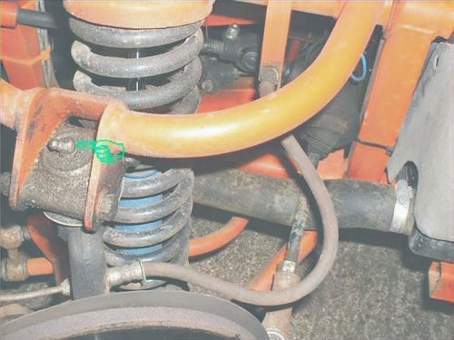
An anti-roll bar is fitted to stiffen up the front on hard cornering - link rods attach this to the front lower rear wishbones (see above).
The dampers were specifically made for the M Series cars by Monroe, but after market types are available from a few performance manufacturers such as Spax and Avo.
The springs are again specifically for the M Series TVR, and it's important to note that the coils are tightly bound and you will need to find a spring compressor that fits correctly if you wish to remove the spring from the damper (some compressors are too thick to fit between the coils). The best type to use is one which attaches to the outside of the spring/damper assembly and acts like a press. See above photo for example showing Monroe damper (from last batch ever produced) and spring (supplied by David Gerald Sportscars Ltd).
The track rod end is "leading" type - i.e. it's in front of the hub rather than
behind (as is more commonly found). Check for play in this joint on every service,
and also make sure the rubber protective boot is free from splits - these joints
will wear out very quickly if dirt is able to get into the joint. At every service
it is worth removing the rubber boot (take off the spring clip), and check the
joint has a good amount of freash looking grease inside.
Servicing
Assuming there are no faults with the front suspension, the two items requiring attention are the grease points (on the top balljoint and bottom trunnion, and front wheel bearing), and to check for any free play in the front wheel bearings.
Grease Points (requires a grease gun)
1) At service time, jack up the front wheel until it is off the ground, and remove the roadwheel.
2) Locate the top & bottom grease nipples, and clean them using a rag or similar so that road dirt/dust isn't injected into the joints.
3) Inject grease into both nipples until clean grease is seen to come out of the joints, and clean off any excess with a rag.
4) Screw a No.10 AF setscrew through the tapped hole in the wheel bearing dust cap and pull on this using a pair of pliers or similar. Pack the wheel bearing with clean grease, but DO NOT pack the dust cap with grease as this gives no space for grease to escape from the bearing and the cap will pop off!
Top balljoint grease point.
Trunnion grease point. Note that you should not use normal
grease for these joints as it will dry out prematurely - resulting in
a faster wear rate and possible failure of the joint. It is better to
use a liquid type grease that will remain thick enough to stay in
the joint, but liquid enough to allow correct lubrication and prevent
drying up.
Regular maintenance
Please take these guides as general procedures only, work safely at all times!
Check Front Wheel Bearings
1) Jack up the front wheel until it is approx. 100mm/4" off the ground.
2) Hold the roadwheel at the top & bottom, and using moderate force rock the wheel to feel for any play. If none, then the bearing and top balljoint are ok, but if there is any more than very slight movement, ask an assistant to sit in the car (make sure you have an axle stand under the chassis) and depress the brake pedal. Now check again for any play. If there isn't any then the wheel bearing requires attention. If there is, it's the top balljoint that requires replacement (the brake locks the disc and thus any play present in the bearing), the trunnion joint, or wishbone bushes. Check each of those in turn to determine fault.
3) Spin the wheel and listen for any grinding noise. If there is any, and you're sure it's not the brake pads rubbing on the disc, then the wheel bearing needs inspection to ascertain whether it's worn out, or has run dry (see procedure for replacement further below).
Adjusting Front Wheel Bearings
On older cars you have the benefit of more components being adjustable and the front wheel bearings on this car are one such item. Use this procedure only if you're sure the wheel bearing is in good condition (i.e. no noise present when spinning the wheel).
1) Remove the front roadwheel, and screw a No.10 AF setscrew through the tapped hole in the wheel bearing dust cap and pull on this using a pair of pliers or similar to remove.
2) Remove the split pin, and try to turn the castellated nut by hand. If it moves more than a fraction then it was too loose, indicating either the bearing has worn a bit since the last service, or the last person to fit the bearing had not done the adjustment correctly.
3) Use a spanner to tighten the nut just past the ''finger tight' position. Spin the disc to check hub spins freely and has no tight spots & doesn't grind. If it's ok, back it off again, then re-tighten using just your fingers. Refit the roadwheel with the centre cap removed and recheck for free play. If movement still present, turn the nut until the next slot lines up with the split pin hole in the stub axle (as you would need to do this anyway). If no play exists now, remove the roadwheel and fit a new split pin in the now lined up hole. If play exists, it will be necessary to remove the disc/hub and inspect the bearings and outer races, as wear is almost certain and replacement necessary.
Replacing Front Wheel Bearings
Replacement of the front wheel bearings is fairly straightforward, as the hub nut is only just finger tight. However, Brake Caliper removal is required to allow the disc and hub flange (which are bolted together) to be pulled from the stub axle.
1) Jack up the car and place an axle stand as an extra precaution under the chassis.
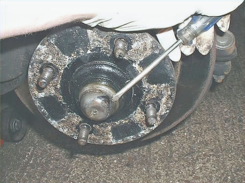
2) Remove the front roadwheel, and screw a No.10 AF setscrew through the tapped hole in the wheel bearing dust cap and pull on this using a pair of pliers or similar to remove (above).
3) If this is too tight to come off, knock the cap off with a cold chisel or similar at an angle as shown.
4) Undo & remove the two bolts (each fitted with a washer and heat shield bracket) that hold the brake caliper onto the stub axle.
4) continued - It may be necessary to press the brake pads in slightly to allow the caliper to be pulled away from the disc (especially if the edge of the disc has a raised "step" caused by wear from the pads. As the flexible brake hose is still attached to the caliper don't let it hang - use a cable tie or piece of string/wire to hang the caliper out of the way.
5) Undo the split pin and then undo the hub nut and remove along with the washer. This will now allow the disc/hub flange to be pulled off the stub axle.
6) Working on a clean workbench, you can remove the brake disc from the hub flange (if required but not necessary) by undoing the four bolts from the rear of the flange (2 can be seen in above photo showing the threaded portion protruding). Each bolt has a washer under its head. An air ratchet and a vice will make light work of this task, otherwise use a suitable ratchet, making sure the hub is securely gripped in the vice. Be careful not to bend the wheel studs, and make sure you are not undoing a bolt with a badly corroded protruding thread as this can strip the thread out of the hub flange.
7) Remove the dust seal retainer and felt seal from the rear of the hub. The inner bearing races on each side of the hub can now be removed, then the outer races should be drifted out using a suitable drift working from the back of each race. Try to tap one side, then the other to "rock" each race slowly out of the hub, and use some penetrating oil (after cleaning the bearing recess walls with degreaser or similar) to make the removal easier. Once they have been removed, clean the inside of the hub flange with degreaser.
8) Clean up the stub axle and check for wear or cracks at this point - it is possible for a seized wheel bearing to spin its inner race sleeve which can wear a groove on the stub axle surface.
9) Once everything is clean and checked to be serviceable, the new wheel bearing can now be fitted. The kit should come with a new dust seal and retainer - the seal needs to be soaked in clean engine oil for a couple of minutes before being fitted to the retainer.
10) With all surfaces spotlessly clean, the outer bearing races can now be fitted to the hub. These have to be squarely inserted, or there is a risk of jamming or even cracking them. Make sure the wider side of each race is outermost, otherwise the inner bearings won't fit. Use the old outer bearing races as drifts if you have nothing else suitable like a hydraulic bearing press, as this will ensure that the surface of the race isn't damaged (using a steel punch will cause dents in the race which will wear out the new wheel bearing much quicker). As with removal, the races can be knocked into place by hitting alternate sides to prevent the race going in twisted. The noise of the hammer will alter once the race has got to its correct place as it will hit the shoulder stop in the hub.
11) Refit the brake disc if removed for this operation.
12) Grease the new bearing inner races fully, and apply some to the outer races in the hub. Both inner races can now be fitted to the outers. Fit the felt seal in its retainer to the inside bearing, making sure the felt faces towards the centre of the car (i.e away from the bearing).
13) Apply a thin layer of grease to the stub axle, then slide the disc/hub complete with bearings & felt seal to the stub axle. Make sure the outer bearing's inner race stays in place as the fitting direction of fitment can make it fall off. Refit the washer and castellated nut to hold the assembly in place.
14) Tighten the hub nut while spinning the disc/hub to allow proper seating of the bearings. Tighten with a spanner to just a bit more than finger tight, then slacken it off to just under finger tight. Keep the disc/hub spinning, then tighten the nut to finger tight, then check for play in the disc by holding it at 3 and 9 o'clock position and rocking it. The amount of play should be very minimal, and the disc should spin freely with no lumpyness or binding. Fit a new split pin top secure the hub nut - and a slight movement of the nut may be required to do this. It's best to tighten it slightly than undo it, AS LONG AS IT'S NOT STARTING TO BIND. Once you're happy with this, bend over the split pin, and refit the hub nut cap. Make sure a little grease is placed over the hub nut area, but don't pack the nut cap with grease as it could fall of due to pressure of excess grease.
15) Refit the brake caliper - referring to the Technical Data page for the correct tightening torque setting of the bolts.
16) Refit the road wheel.
17) After a short test drive, jack up the car again and recheck for play - just to be sure the bearing has seated correctly. Adjust the bearing again if necessary, but it's unusual for a second adjustment to be necessary.
Front trunnion steering stop - make sure this is fitted & not sheared off on both sides. Crash or obstacle impact when steering is on full lock can damage these if the impact is large enough.
Jacking point for front suspension. When I restored the chassis I added 3mm steel plates to this area to prevent chassis damage when taking to the tyre shop.


Suspension/Steering Data
Geometry Set-Up
Toe In
Camber
Front Suspension/Steering Attachments
Brake Disc to Hub Flange
Brake Caliper to Vertical Link
Caliper Mounting Plate to vertical link
Steering Tie Rod Cast Arm to vertical link
Lower Wishbones to Vertical Link Trunnion
Stub Axle to Vertical Link
Top Balljoint to Upper Wishbones
Top Balljoint to Vertical Link
Wheel Nuts
Rear Suspension/Drive Attachments
Rear Hub
Inner Half Shaft Flange to Diff Output Flange (TR6 Diffs)
Tyre Pressures (Standard Size Only 185 x 14)
1600M
2500M
3000M
3000M Turbo
3000S
Advised Angles
0º30' or 1/8"
0º to 0º30' negative
Advised Torque
32 to 35 lb/ft (4.42 to 4.84 Kg/m)
50 to 55 lb/ft (6.91 to 7.60 Kg/m)
26 to 28lb/ft (3.60 to 3.87 Kg/m)
as per caliper Mount Plate - same bolts
45 to 60 lb/ft (6.22 to 8.30 Kg/m)
55 to 60 lb/ft (7.60 to 8.30 Kg/m)
26 to 28 lb/ft (3.60 to 3.87 Kg/m)
55 to 65 lb/ft (7.60 to 8.99 Kg/m)
55 to 60 lb/ft (7.60 to 8.30 Kg/m)
Advised Torque
100 to 110 lb/ft (13.83 to 15.21 Kg/m)
28 to 30 lb/ft (3.87 to 4.15 Kg/m)
Pressure (Front) Pressure (Rear)
22 lb/sq. in. 24 lb/sq in.
22 lb/sq. in. 24 lb/sq in.
24 lb/sq. in. 26 lb/sq in.
24 lb/sq. in 26 lb/sq in.
24 lb/sq. in. 26 lb/sq in.